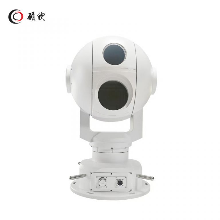
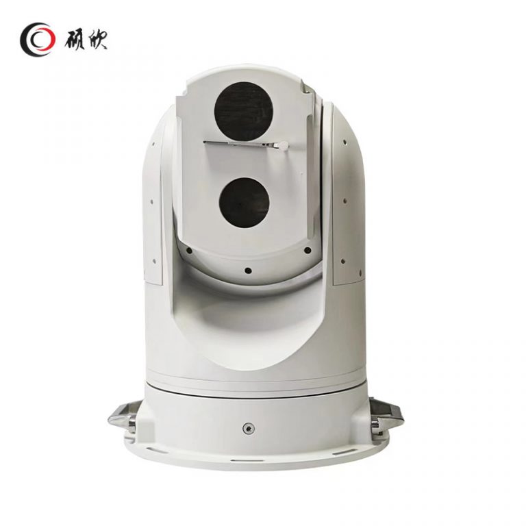
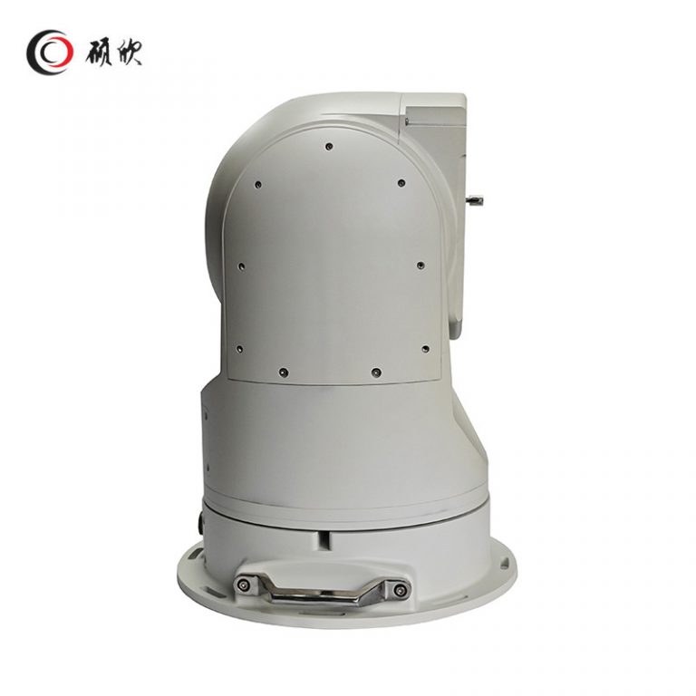
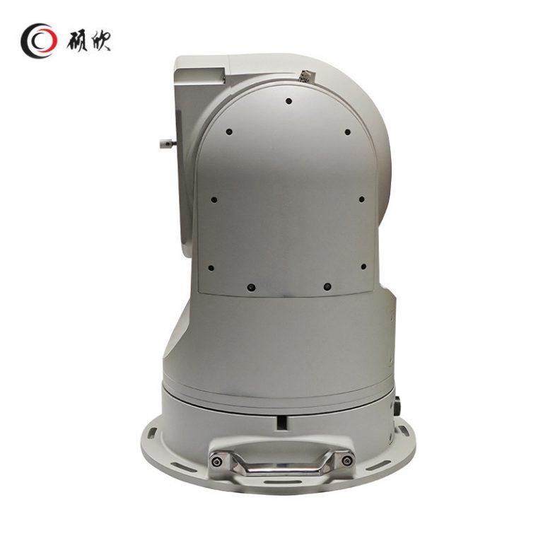
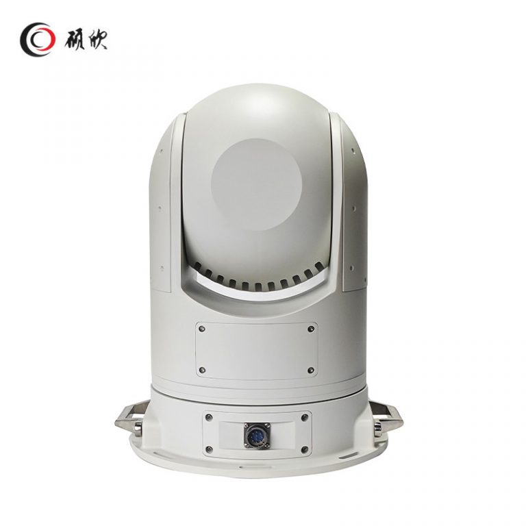
WL-HB988 combines a 2 MP visible camera, thermal imaging and two-axis gyro stabilization for marine PTZ projects. Configuration begins with the vessel-motion task; laser ranging remains an expressly optional item.
WL-HB988 combines 2 MP visible imaging, thermal imaging and two-axis gyro stabilization. Its visible channel uses 52× optical zoom; the thermal channel is 640 × 480 with a 75 mm lens. Continuous pan, -90° to +90° tilt, ONVIF/SDK, RS422, DC 24 V and IP67 form the documented baseline. The 1,000 m laser rangefinder is optional.
Select WL-HB988 around vessel motion and optional ranging. Define that task before comparing options.
Build the operator sequence around vessel motion and optional ranging; state the view, detail and mode change needed.
Listed uses range from vessels and coastal observation to maritime search, airports, border work, fan-blade or photovoltaic inspection and fire warning. Each project still has to define the vessel structure, observation task and receiving system.
Put 15 kg marine support on the drawing and leave unresolved mechanics pending.
Map DC 24 V, RS422 and ONVIF to host functions one by one rather than relying on names.
Check installed power and cabling; keep optional rangefinder separate until confirmed.
Send vessel motion and optional ranging, 15 kg marine support and DC 24 V, RS422 and ONVIF; flag optional rangefinder for confirmation.
| thermal imaging camera | Sensor type | Vanadium Oxide Uncooled Detector |
| Effective pixels | 640*480 | |
| Focal length | f=75mm | |
| Aperture | F1.0 | |
| Pixel size | 12μm | |
| Response band | 8~14 μm | |
| NETD | <35 mk | |
| Electronic amplification | ×1,×2,×4,×8 | |
| Visible light camera | imager | 1/1.8″Progressive scanning CMOS image sensor |
| Effective pixels | 1920×1080P | |
| Focal Length | 6.1-317mm,52X Optical Zoom | |
| illuminance | Starlight level ultra-low illumination, no fill color 0.0005LUX black and white 0.00001LUX | |
| automatic control | Automatic white balance, automatic gain, automatic exposure | |
| Signal to Noise Ratio | ≥55dB | |
| Wide Dynamic | 120dB | |
| PTZ | Pan range | 360°Continuous rotation |
| Pan speed | 0.05°~400°/s | |
| Tilt range | -90°~+90°rotate | |
| Tilt speed | 0.05°~200°/s | |
| Scaling | support | |
| Preset | 256 | |
| Cruise scanning | 6 | |
| Wiper | support | |
| Image stabilization function | Gyroscopic stabilization | biax |
| steady-state accuracy | 0.1° | |
| Maximum carrier following speed | 100°/s | |
| Other function | Audio input and output | support |
| Alarm input and output | 1way | |
| External data interface | RS422 | |
| laser ranging | optional | |
| Laser ranging distance | 1000m(optional) | |
| Laser ranging accuracy | 1m | |
| Power | DC24V 5A±15%,50Hz | |
| consume power | maximum power 60W | |
| protection grade | IP67 | |
| electromagnetic compatibility | 6KV GB/T 17626.5 -4 | |
| operation temperature | -40℃~70 ℃ | |
| Working humidity | Humidity less than 90% | |
| weight | 15KG |
Related products are grouped in the New Product category. Compare the imaging task, mounting, power and control route together rather than selecting on one distance or zoom figure.
Begin with vessel motion and optional ranging.
Check DC 24 V, RS422 and ONVIF against required host functions.
Show 15 kg marine support, cables and clearances.
Keep optional rangefinder unresolved until written confirmation.
Describe how the operator will move between the 2 MP visible channel and the thermal view while the vessel is moving. Two-axis gyro stabilization belongs in that operating sequence. Laser ranging does not: the page marks the 1,000 m rangefinder as optional, so an inquiry that needs range data must request that option expressly.
The installation drawing should carry the 15 kg unit load, the full pan circle and the -90° to +90° tilt sweep. Add the fixing surface, service access and cable exit chosen by the vessel designer. Those details determine whether the camera can move freely after the support and surrounding equipment are installed.
On the electrical sheet, identify the DC 24 V feed separately from RS422 control and the ONVIF network path. The receiving equipment must be checked for the functions actually required. Do not treat the appearance of an interface name as proof that every host command has already been mapped.
Release the request only when the visible/thermal operating sequence, deck support and cable route refer to the same WL-HB988 build. The optional rangefinder must appear either as an expressly requested item or as excluded. Confirm power at the camera connection and keep site-specific mounting details in the vessel drawing.
For a project that does request ranging, describe where the range value will be used and how the operator reaches that function. Keep the rangefinder line separate from the baseline 52× visible and 75 mm thermal channels. This prevents an optional sensor from being mistaken for standard equipment while allowing the RS422 or ONVIF control review to continue.
Use Contact Us to send vessel motion and optional ranging, the drawing and required functions. Identify the optional rangefinder as pending and include the planned deck cable entry.